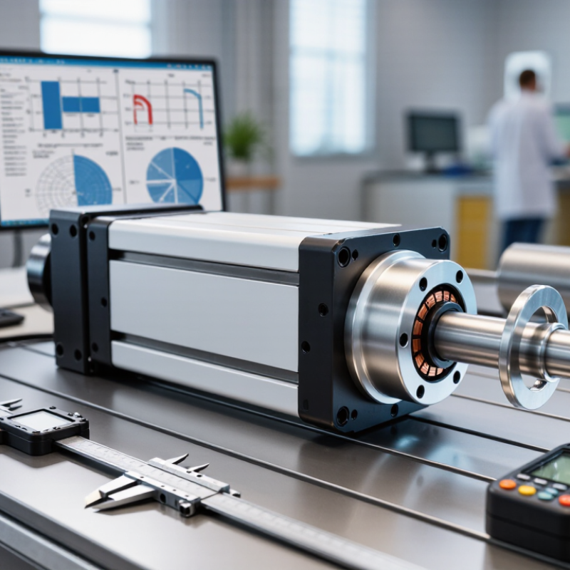
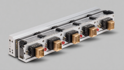
Choosing a voice coil linear actuator begins with the motion profile, not the catalog photograph. Engineers must compare continuous force, peak force, stroke, acceleration, thermal limits, feedback resolution, and duty cycle. A compact actuator may deliver rapid, frictionless movement, yet its coil can heat quickly during repeated cycles. That detail matters.
MarketsandMarkets’ Voice Coil Motor Market analysis identifies medical equipment, industrial automation, automotive systems, and aerospace as important application areas. Grand View Research also reports continued growth in the broader linear motor market, driven by precision manufacturing and automated inspection. These reports show commercial momentum, but they do not replace application testing. A clean spreadsheet can still hide resonance, cable drag, or insufficient cooling.
Motion-control engineer John Rinaldi has repeatedly stressed a practical principle: “You can’t control what you can’t measure.” That idea fits voice coil linear actuator selection closely. Without a position sensor, force measurement, or dependable load data, performance claims remain incomplete. I would not treat a high peak-force rating as proof of suitability. It may describe a brief test, not an eight-hour production cycle.
This guide examines actuator construction, magnetic circuits, force constants, stroke length, thermal behavior, feedback options, and controller compatibility. It also considers mounting stiffness and the actual payload. Small details decide reliability. The best choice is rarely the largest actuator. It is the one that delivers predictable force, stable positioning, and acceptable temperature under real operating conditions.
Choosing a voice coil linear actuator starts with a precise motion definition. State the required stroke, peak force, continuous force, speed, and acceleration. A 10 mm stroke at 50 mm/s needs different sizing from a 10 mm stroke at 500 mm/s. Measure the moving load, not only the actuator’s weight. Include friction, spring resistance, cable drag, and gravity. The first estimate is rarely right. Check it again.
Operating conditions can change performance quickly. Record the duty cycle, mounting direction, ambient temperature, humidity, dust, vibration, and available voltage. A vertical mechanism needs force to lift the load and hold it safely during motion. High-cycle operation may create heat, even when the average force seems modest. Thermal rise matters. Do not size from peak force alone. During one bench test, a compact actuator reached its force target but became too warm for continuous use. That result changed the required duty cycle.
Match the actuator to the real motion profile rather than a simplified average. Define acceleration ramps, settling time, repeatability, and allowable overshoot. For precise positioning, plan the sensor location and control response early. Feedback can reveal small errors caused by load changes or mechanical flex. Leave a practical margin, but avoid excessive oversizing, which can reduce efficiency and control sensitivity. A short, instrumented test with the actual load often exposes assumptions that calculations miss.
How to Choose a Voice Coil Linear Actuator?
Voice coil actuators use electromagnetic force for direct, precise linear motion. Their simple structure removes gears, backlash, and mechanical transmission losses. Moving-coil designs usually offer lower moving mass and faster response. Moving-magnet designs can simplify wiring to the moving assembly. The correct choice depends on stroke, force, speed, duty cycle, and position accuracy.
Iron-core actuators produce stronger force in a compact package. However, magnetic attraction can increase friction and reduce smoothness. Ironless designs provide cleaner motion and excellent repeatability. They usually require more space or higher current. According to a 2024 Grand View Research analysis, the voice coil motor market is expected to grow at more than 6% annually through 2030. This trend reflects demand for compact motion systems in medical equipment, optics, and automation.
Check the force constant first. A 5 N load may need far more than 5 N during acceleration. Thermal limits matter just as much. The actuator may reach its force rating briefly, but continuous operation can cause coil heating. IEC 60034-1 emphasizes temperature-rise limits for electrical machines, although voice coil assemblies need application-specific testing. Measure stroke, settling time, and temperature under real loads. A clean spreadsheet can still mislead. Cable stiffness, mounting alignment, and controller tuning often change the result. In practice, the “best” actuator is rarely the strongest one.
Selecting a voice coil linear actuator starts with the required force, stroke, speed, and acceleration. Define the moving mass before choosing a model. Force must overcome load, friction, gravity, and acceleration.
Add a sensible margin, but avoid excessive oversizing. It increases cost and can reduce control sensitivity.
Stroke describes the actuator’s usable travel. Include clearance at both ends. A 20-millimeter motion may need a longer mechanical envelope. Speed affects cycle time, while acceleration determines how quickly the load reaches that speed. High acceleration demands more force and may cause vibration in flexible assemblies.
I once focused only on peak speed and underestimated settling time. The mechanism performed quickly, but the final position was inconsistent.
Check continuous force, peak force, duty cycle, and thermal limits together. Peak force may last milliseconds, while continuous force can operate for extended periods. Repeated rapid cycles create heat in the coil. Measure the real load, not only the catalog estimate. Keep cables flexible and confirm that guides can handle side loads. The actuator should not carry unwanted lateral forces. Test at the highest temperature and with the heaviest expected load. A small safety margin is useful. An oversized margin is not always better.
How to Choose a Voice Coil Linear Actuator?
Evaluate Electrical, Thermal, and Mechanical Compatibility
Choosing a voice coil linear actuator starts with the actual motion profile. Define stroke, peak force, continuous force, speed, acceleration, and duty cycle. A unit may reach the required peak force but overheat during repeated movement. Check the force constant, coil resistance, inductance, and driver voltage together. Current creates force, while resistance produces heat. These values cannot be judged separately.
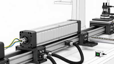
Thermal compatibility often decides long-term reliability. Estimate I²R losses during the complete operating cycle, not only during peak movement. Measure coil temperature with a sensor during realistic testing. Allow for ambient temperature, mounting material, airflow, and nearby heat sources. A metal housing can improve heat transfer, but only when the contact surfaces are properly designed. Small details matter. Mechanical compatibility includes stroke limits, moving mass, guidance, side loads, and mounting stiffness. Voice coil actuators generally perform best with accurate external guidance. Side loading may cause friction, wear, or unstable motion.
Tips: Test the actuator under real acceleration and pause times. Compare measured temperature with the permitted coil temperature. Review the driver’s current limit and control bandwidth. Leave force margin, but avoid excessive oversizing. It adds mass and cost. A theoretical match can still fail in practice. Early prototypes sometimes reveal unexpected vibration, cable drag, or resonance. Recheck the calculations after testing, because the first assumptions may be incomplete.
Evaluate Electrical, Thermal, and Mechanical Compatibility
The chart shows representative compatibility margins for three generic actuator configurations. Higher values indicate more remaining design margin against the application limits. Electrical margin considers continuous and peak current, thermal margin considers allowable temperature rise, and mechanical margin considers force, stroke, and velocity requirements. Always verify final values against the selected actuator’s datasheet and operating duty cycle.
How to Choose a Voice Coil Linear Actuator?
A voice coil actuator should match the control architecture, not just the force rating. The U.S. Department of Energy’s 2022 Motor Systems Market Assessment estimates motor-driven equipment uses about 68% of industrial electricity. Efficient control matters. Check whether the amplifier supports current control, peak force, continuous force, and the required duty cycle. Confirm acceleration limits and settling time under the real load. A spreadsheet is not enough.
Feedback deserves equal attention. Select an encoder with suitable resolution, bandwidth, and repeatability for the motion profile. Check signal compatibility with the controller and define what happens after power loss. The 2024 World Robotics report recorded 541,302 industrial robot installations worldwide in 2023. That growth increases demand for predictable positioning, but tighter motion does not automatically mean better accuracy. Cable routing, electrical noise, and filtering can quietly reduce performance.
Mounting errors are common. Keep the actuator aligned with its guide, and prevent side loads from reaching the moving shaft. Use measured tolerances, not hopeful assumptions. Inspect cable bends, connectors, guide wear, and mounting bolts during scheduled maintenance. Many voice coil assemblies need little actuator maintenance, but their guides may require cleaning or lubrication. Environmental reports are often overlooked. Verify temperature, dust, moisture, and shock ratings before purchase. I would also test a prototype for several thousand cycles. The first design is rarely perfect.
Use this selection matrix to compare application requirements with the actuator, amplifier, feedback, mechanical, thermal, and maintenance conditions that must be verified before specification.
| Requirement Area | Selection Criterion | What to Verify | Typical Engineering Guidance | Recommended Validation Method | Selection Risk |
|---|---|---|---|---|---|
| Motion Performance | Continuous and peak force | Check the required force profile, including acceleration, friction, external load, gravity, preload, and cable drag. | Size continuous force for the thermal operating point and peak force for short acceleration or disturbance events. Do not use peak force as the continuous rating. | Calculate the force-time profile and compare both RMS force and maximum force with the actuator datasheet. | High: undersizing can cause overheating or loss of motion. |
| Motion Performance | Stroke and travel limits | Confirm usable stroke, mechanical end stops, required clearance, home position, and over-travel protection. | Choose a usable stroke greater than the commanded travel when settling distance, tolerances, or safety margin are required. | Review the mechanical envelope and perform a full-travel test at the highest expected speed. | High: insufficient travel may cause impact at the end of stroke. |
| Motion Performance | Speed, acceleration, and bandwidth | Verify maximum velocity, acceleration, move frequency, settling time, and the required servo-loop bandwidth. | Higher acceleration increases force demand. Dynamic performance depends on actuator force, moving mass, amplifier current, feedback resolution, and mechanical stiffness. | Test the complete actuator-load system using the actual motion profile and load inertia. | High: a suitable actuator may still fail if the control loop is too slow. |
| Control | Drive and current capability | Match the actuator's coil resistance, inductance, continuous current, peak current, voltage, and amplifier output mode. | Voice coil actuators are commonly controlled by current because force is approximately proportional to coil current within the specified operating range. | Confirm electrical limits from the actuator and amplifier data, then verify current waveform with a calibrated measurement system. | High: excessive current can rapidly increase coil temperature. |
| Control | Position, velocity, or force mode | Determine whether the application needs closed-loop position, velocity, force, or a coordinated multi-axis control mode. | Position control generally requires a position sensor and servo controller. Force control may require a load cell, force sensor, or a validated indirect force estimate. | Define the control architecture, sampling rate, command interface, limits, and fault response before final selection. | Medium: an actuator alone does not provide a complete motion-control system. |
| Feedback | Sensor type and resolution | Check sensor technology, resolution, repeatability, linearity, electrical interface, update rate, and cable routing requirements. | Feedback resolution must be finer than the required positioning tolerance. The achievable system accuracy also depends on calibration, stiffness, friction, and thermal drift. | Measure repeatability and positioning error over the full stroke at operating temperature. | High: sensor resolution alone does not guarantee system accuracy. |
| Feedback | Commutation and initialization | Verify whether the actuator requires commutation information, a home routine, an index signal, or absolute position feedback. | Some systems require an initialization sequence after power-up, while absolute feedback can reduce or eliminate the need for a homing move. | Test startup, power loss, sensor disconnection, and recovery behavior under controlled conditions. | Medium: incorrect initialization can produce unexpected motion. |
| Mechanical Mounting | Alignment and side-load control | Check parallelism, concentricity, bearing guidance, moving mass support, and allowable radial or lateral load. | Voice coil actuators generate linear force but normally should not be used to guide a load. External guides should carry side loads and moments. | Inspect alignment with suitable measurement tools and verify force, friction, and vibration during the complete stroke. | High: misalignment can increase friction, wear, and positioning error. |
| Mechanical Mounting | Fasteners, stiffness, and resonance | Confirm mounting-hole pattern, fastener grade, tightening torque, structural stiffness, natural frequency, and access for service. | Mounting structures should be sufficiently stiff to prevent resonances within the control bandwidth and should not obstruct the actuator's moving section. | Perform a vibration or frequency-response check after installation and inspect fasteners during commissioning. | Medium: structural resonance can reduce stability and settling performance. |
| Thermal Management | Duty cycle and temperature rise | Verify ambient temperature, duty cycle, RMS current, heat dissipation path, allowable coil temperature, and nearby heat sources. | Continuous operation is limited by heat generation and thermal resistance. A lower duty cycle or improved heat sinking may be required for high-force applications. | Measure coil or housing temperature after the application reaches thermal equilibrium under the worst-case cycle. | High: thermal limits are often more restrictive than peak force limits. |
| Environment | Contamination and ingress protection | Check dust, moisture, oil, coolant, cleaning agents, vacuum conditions, shock, vibration, and required ingress protection. | Actuator construction and sealing must match the environment. Open magnetic and moving assemblies may require guarding or a protective enclosure. | Review the environmental specification and test the installed assembly using representative contaminants and operating conditions. | High: contamination can affect guides, sensors, magnets, and moving clearances. |
| Maintenance | Lubrication and wear components | Identify bearings, guideways, seals, flexures, cables, and other components that may require inspection, lubrication, or replacement. | Maintenance intervals depend on load, speed, contamination, lubrication type, and duty cycle. Flexure-based guidance can reduce sliding wear but has travel and fatigue limits. | Create an inspection schedule based on cycle count, temperature, noise, friction, position error, and visible wear. | Medium: neglected guides or cables can degrade performance before actuator failure. |
| Safety and Reliability | Fault handling and fail-safe behavior | Verify overcurrent, overtemperature, over-travel, sensor-fault, emergency-stop, power-loss, and unexpected-restart behavior. | Define a safe state for loss of feedback or amplifier power. A voice coil actuator may not hold position without active control or a separate mechanical brake. | Run fault-injection tests and confirm that the machine meets the applicable risk assessment and safety requirements. | High: power loss may allow uncontrolled movement depending on orientation and load. |
| Documentation | Data and integration records | Obtain electrical, mechanical, thermal, feedback, wiring, calibration, and maintenance information for the complete assembly. | Use application-specific limits rather than nominal values alone. Record load, motion profile, ambient conditions, mounting arrangement, and control parameters. | Complete a design review and retain test results, calibration records, wiring diagrams, and preventive-maintenance instructions. | Low when all requirements are documented and validated. |

Note: Actual force, stroke, speed, current, temperature, sensor, and environmental limits must be confirmed from the selected actuator's technical documentation and validated in the final mechanical and control system.
Sierramotion engineers help customers design solutions to complex motion problems. Whether a simple coil, or a precision motion assembly working in vacuum, Sierramotion has the experience to create a solution that works the first time.