
Choosing a wafer type butterfly valve can look simple beside a pipe rack. It is not. The correct choice depends on pressure, temperature, media, pipe alignment, and maintenance access. A valve that works perfectly with clean water may fail quickly in abrasive slurry. Its seat may swell, harden, or lose sealing force.
Valve specialist R. W. Zappe emphasizes, “Valve selection must follow the process, not the catalogue.” This principle gives the following seven tips practical direction. Check the line size and pressure class first. Then examine the fluid carefully. Is it corrosive, abrasive, viscous, or carrying suspended solids? These details influence the disc material, shaft design, and seat compound.
Look closely.
A reliable wafer type butterfly valve should match the pipeline’s flange standard and available installation space. Measure the face-to-face distance before ordering. Confirm whether the valve needs a manual handle, gearbox, pneumatic actuator, or electric actuator. Consider emergency shutoff requirements, cycling frequency, and available air pressure. A small mismatch can create leakage, difficult operation, or expensive downtime.
Do not trust a catalogue image alone. Ask for pressure-temperature ratings, seat compatibility data, test documentation, and installation guidance. Review the supplier’s manufacturing experience and quality controls. An apparently cheaper valve may require earlier replacement. That is not always true, but ignoring lifecycle cost is a common mistake. The best decision combines field experience, engineering evidence, and honest questioning. Even experienced buyers should revisit assumptions before approving the final specification.
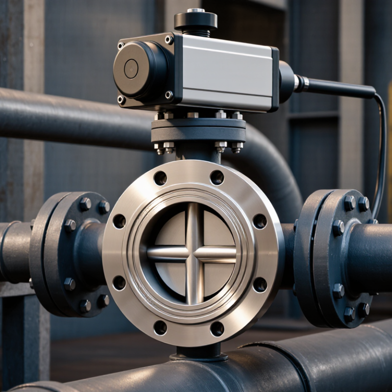
Choosing a wafer butterfly valve starts with the line, not the catalog. Confirm the fluid, pressure, temperature, pipe size, and available space. A wafer valve fits between flanges, so check the flange pattern carefully. Small mismatches can create large installation problems.
Read API 609 for butterfly valve design, pressure class, testing, and performance expectations. EN 593 addresses industrial metallic butterfly valves and may suit European project specifications. ISO 5752 mainly controls face-to-face dimensions, helping the valve fit existing piping. These standards overlap, but they are not interchangeable. Ask for the exact edition and compliance documents. Do not accept “standard design” as proof.
Check the body material against corrosion risks. Match the seat material to temperature and chemical exposure. Select the disc and stem for required pressure and operating frequency. Verify the ISO 5752 face-to-face dimension before ordering. Confirm flange compatibility, including bolt holes and gasket contact. Request pressure-test records and material certificates. Finally, examine the actuator interface and emergency operating method.
Keep the handle clear.
In field inspections, I have seen valves chosen correctly on pressure but poorly on seat compatibility. That mistake is easy to overlook. A polished datasheet can still hide an unsuitable temperature limit. I also revisit valve sizing after reviewing actual flow conditions, because nominal pipe size is not enough. When uncertainty remains, involve a qualified engineer and record the decision basis. That record improves reliability during installation, commissioning, and future maintenance.
Choosing a wafer butterfly valve begins with pressure class, not face-to-face dimensions. ASME B16.34 Classes 150, 300, and 600 are pressure-temperature ratings, not direct bar values. The allowable pressure changes with body material, temperature, and fluid service. Always read the relevant material group table.
Do not size from the pipeline’s normal pressure alone. A pump start, rapid shutdown, or blocked outlet can create a short pressure surge. A valve rated Class 150 at ambient conditions may lose capacity as temperature rises. Check the ASME B16.34 rating at the maximum operating temperature, then compare it with the design pressure and upset conditions. Leave a practical margin.
API 609, 2021 edition, provides widely used requirements for butterfly valve design, dimensions, and testing. It should support, not replace, the project specification. In field reviews, one recurring mistake is selecting Class 300 because “300” sounds safely high. It may still be unsuitable for hot service or severe cycling. Verify flange compatibility, bolt loads, seat limitations, and hydrostatic test requirements.
Small details matter. A wafer body sits between flanges, but it does not upgrade their pressure class. Consult certified material data and the latest standard editions. I would also question vendor pressure charts that omit temperature corrections. That omission is easy to miss. It can become expensive.
At 200°C, temperature is not a label; it is a mechanical load. IAPWS-IF97 data places saturated steam at approximately 1.55 MPa absolute at 200°C. That pressure can expose weak sealing choices quickly. API 609 defines butterfly valve design requirements, but it does not select the correct disc or seat material for every service.
For the disc, 316L stainless steel is a practical choice for many hot-water and clean-process lines. Chloride-rich fluids need more caution because pitting can develop beneath deposits. Duplex stainless steel may offer better resistance, but compatibility depends on chemistry, stress, and fabrication quality. A polished disc also reduces deposits around the shaft area. Small details matter.
The seat deserves closer attention. Standard EPDM is commonly limited below 200°C, especially in continuous steam service. PTFE offers strong chemical resistance, but creep and deformation can increase near its upper temperature range. Reinforced PTFE or PEEK may perform better, subject to pressure and media limits. For sustained high-temperature steam, a metal seat can be more dependable, although its leakage performance differs from soft seats. ISO 5208 leakage testing helps verify that difference. A neat material chart is not enough. Check thermal cycling, pressure, shaft sealing, and chemical exposure together. I would also question a “200°C rated” valve when the rating excludes continuous operation, vacuum, or frequent cycling. That missing detail can become the expensive part.
| Seat Material | Typical Continuous Temperature Range | Recommended Disc Materials | Suitable Applications | Key Advantages | Important Limitations | Selection Guidance |
|---|---|---|---|---|---|---|
| EPDM | −40°C to +130°C | Stainless steel; epoxy-coated ductile iron; aluminum bronze | Cooling water, hot water, dilute acids, alkalis, and many water-treatment services | Excellent resistance to hot water, steam at appropriate conditions, ozone, and weathering | Not suitable for petroleum oils, mineral oils, fuels, or most hydrocarbon-based fluids | Choose EPDM when the medium is water-based and the operating temperature remains below approximately 130°C. |
| NBR | −20°C to +100°C | Stainless steel; nickel-plated ductile iron; aluminum bronze | Air, water, hydraulic fluids, lubricating oils, and selected hydrocarbon services | Good resistance to mineral oils, fuels, and abrasion; generally cost-effective | Limited resistance to ozone, weathering, aromatic hydrocarbons, and high-temperature water or steam | Use NBR for oil-containing media when the temperature is controlled below approximately 100°C. |
| FKM | −20°C to +150°C; some compounds up to +200°C | Stainless steel; nickel-plated ductile iron; aluminum bronze | Hydrocarbons, fuels, mineral oils, many chemicals, and high-temperature process fluids | Strong resistance to oils, fuels, many chemicals, and elevated temperatures | Unsuitable for hot water or steam in many formulations; limited resistance to some amines, ketones, and hot concentrated acids | Select the exact FKM compound from its temperature and chemical compatibility data when approaching 200°C. |
| PTFE | −40°C to +200°C | 316 stainless steel; Hastelloy-type nickel alloy; aluminum bronze where compatible | Corrosive chemicals, aggressive process fluids, high-purity services, and many solvent applications | Very broad chemical resistance and low friction; suitable for high-temperature chemical service | May deform or creep under high pressure and temperature; poor resistance to some molten alkali metals and elemental fluorine | Consider PTFE for chemically aggressive media up to 200°C, while checking pressure, cycling, and seat-load requirements. |
| Silicone Rubber | −50°C to +180°C | Stainless steel; aluminum bronze | Dry air, hot gases, selected food or pharmaceutical services, and applications requiring wide temperature flexibility | Excellent flexibility over a wide temperature range and good resistance to weathering and ozone | Lower tear and abrasion resistance; limited resistance to many oils, fuels, and high-pressure steam | Use silicone only when the process fluid and mechanical loading are confirmed suitable; it is not a general-purpose oil seal. |
| Metal-Seated Design | Typically up to +200°C or higher, depending on construction | Stainless steel; nickel alloy; heat-resistant alloy | Dry gases, abrasive fluids, high-temperature process lines, and services where elastomer seats are unsuitable | Better resistance to heat, abrasion, and certain mechanical loads than soft seats | Higher leakage than resilient seats may occur; sealing performance depends strongly on machining, alignment, and thermal expansion | Choose a metal seat when temperature, abrasion, or fire-related requirements exceed the practical limits of elastomer seats. |
Choosing a wafer butterfly valve starts with more than matching the pipe diameter. I have seen installations fail because the valve size was selected from the line label alone. Confirm the nominal pipe size, pressure class, temperature, and operating medium. A 100 mm pipe does not always require a 100 mm valve.
Face-to-face dimensions deserve equal attention. Measure the available gap between the flanges, including gasket space and possible insulation. Wafer valves are compact, but small dimensional errors can force pipe stress or prevent proper disc movement. Check the applicable dimensional standard and compare the supplier’s certified drawing with the actual piping layout. Do not rely on an old project file. It may be wrong.
Flow capacity needs a practical review. Request the valve’s Cv or Kv data, then compare it with the required flow rate and allowable pressure drop. Water, air, steam, and corrosive liquids behave differently. Excessive velocity can create noise, vibration, erosion, or unstable control. A valve that is too large may also operate poorly at low flow. I once accepted a generous size margin and overlooked minimum operating flow. That shortcut caused weak control near the setpoint. Review normal, minimum, and maximum conditions, not only the peak value. A site engineer should verify the calculation before ordering. Small details matter.
Torque comparison should begin with operating points, not one headline number. EN 15714-2:2010 separates opening, running, and closing torque for part-turn actuators. ISO 5211:2024 defines actuator-to-valve interfaces, but it does not replace valve torque testing. Do not trust catalog torque alone.
Consider an illustrative commissioning record for a 100 mm wafer butterfly valve. Breakaway torque measured 42 Nm, running torque 28 Nm, and seating torque 35 Nm. A 25% engineering allowance produces a target near 53 Nm. A manual lever may achieve this torque briefly, but operator strength and access can vary. Pneumatic output changes with supply pressure, spring action, and the actuator torque curve. At 5.5 bar, an example actuator might deliver 68 Nm at opening, then fall to 54 Nm near travel completion. Electric actuators need separate breakaway, rated, and seating figures. A unit rated at 60 Nm may still fail if its starting torque is only 45 Nm.
Field data deserves more attention than advertising language. API 609:2022 provides widely used requirements for butterfly valves, while IEC 60034-1 supports motor performance and duty evaluation. Check actual pressure, temperature, media, and cycle frequency. Sediment can raise breakaway torque sharply. That detail is easy to miss. A weak sizing worksheet often compares only maximum actuator torque with nominal valve torque. That is incomplete, and sometimes misleading. Record torque at 0°, 30°, 60°, and 90° whenever possible. Recheck the margin after installation.
Choosing the right wafer type butterfly valve requires more than selecting a suitable nominal size. Start by confirming that the valve design complies with relevant standards, such as API 609, EN 593, and ISO 5752, which help define construction, dimensions, and installation compatibility. Pressure ratings should be matched carefully, from ASME B16.34 Class 150 through Class 600, according to the system’s operating pressure and safety requirements.
Material selection is equally important. Disc and seat materials must withstand the expected medium and temperatures up to 200°C without excessive wear or deformation. Verify the valve size, face-to-face dimensions, and flow capacity to ensure proper pipeline fit and efficient operation. When selecting an actuator, compare the required torque with the performance data of manual, pneumatic, and electric options. Finally, check leakage performance against ISO 5208 Rate A criteria to support reliable shutoff and long-term service. A complete evaluation of these factors helps ensure safe, efficient, and durable valve operation.

Sierramotion engineers help customers design solutions to complex motion problems. Whether a simple coil, or a precision motion assembly working in vacuum, Sierramotion has the experience to create a solution that works the first time.