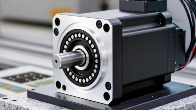
How to Choose the Right Linear Motion Motor?
Choosing the right linear motion motor begins with the machine’s real working conditions, not a product catalog. A packaging axis may need rapid acceleration, while a laboratory stage may demand quiet, repeatable positioning. Load mass, stroke length, duty cycle, speed, force, and mounting space must be measured carefully. Small errors matter.
Jacek F. Gieras, a recognized researcher and author in electric machine technology, explains the basic concept clearly: “A linear motor is an electric motor unrolled into a straight line.” This idea helps engineers compare linear motors with rotary motors, belts, screws, and pneumatic systems. Yet the comparison is not always simple. A linear motor can deliver smooth direct motion without mechanical transmission, but it may require precise feedback, thermal control, and a suitable amplifier. More performance can also mean more design responsibility.
Look at the application in physical terms. Imagine a carriage moving 600 millimeters, stopping within 10 micrometers, several hundred times each hour. Friction, cable drag, heat, and vibration will influence the result. The motor’s peak force may appear impressive, but continuous force usually determines dependable operation. Check the encoder resolution, bearing arrangement, cooling method, and controller compatibility. Do not trust speed figures alone.
A practical selection process should include calculations, supplier data, and testing under actual loads. This is where experience matters. Some choices will remain imperfect. Real machines rarely match ideal specifications. Build a small test axis when possible, record temperature and settling time, then revise the design before production. Reliability is not a single number. It is repeated performance in the environment where the linear motion motor must work.
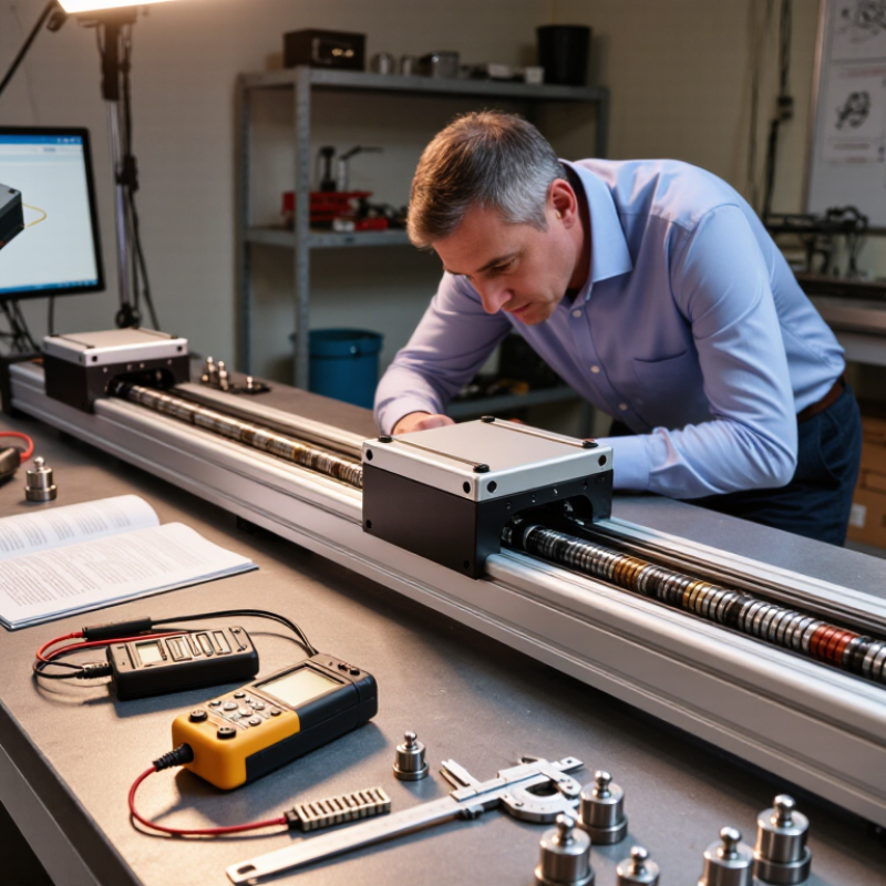
Define Motion Requirements: Force F=ma, Speed, Stroke, and Duty Cycle
How to Choose the Right Linear Motion Motor?
Define the motion requirements before comparing motor specifications. Start with the moving mass, acceleration, friction, and travel direction. Use F = ma to estimate acceleration force. Then add friction and gravity when the axis moves vertically or along an incline. A horizontal slide may need modest force, while a vertical lift can demand much more. Include a suitable safety margin, but avoid choosing an oversized motor without checking heat and efficiency.
Speed and stroke also shape the selection. Specify both average speed and peak speed, because they may differ sharply during acceleration. Measure the complete stroke, including settling distance and mechanical clearance. A short stroke at high speed can create greater acceleration demands than a slow, long movement. Duty cycle matters too. Calculate how long the motor runs, rests, and repeats within one operating period. Continuous motion may require a different thermal capacity than ten brief movements per hour.
Tips: Write a simple motion table with mass, force, speed, stroke, cycle time, and rest time. Check peak force and continuous force separately. Do not trust a perfect spreadsheet blindly. Real friction changes with alignment, lubrication, and temperature. A rough estimate can still be useful, but it should be tested with measured current, vibration, and stopping accuracy. Recheck the calculation after prototype testing. მთავრობის
Compare Motor Types by Force Density, Accuracy, and Peak/RMS Force
Choosing the Right Linear Motion Motor
Motor selection should begin with force density, not catalogue force alone. Force density shows how much thrust fits inside the available machine space. Iron-core motors often deliver strong thrust in compact assemblies, but their magnetic attraction can increase bearing loads. Ironless designs usually provide smoother motion and lower cogging, although they may require more installation space. Voice-coil motors suit short strokes and rapid, controlled movements. They are simple, but continuous force can be limited by coil heating.
Accuracy depends on more than the motor. Encoder resolution, guide straightness, mounting stiffness, and servo tuning all affect the final position. A high-resolution encoder cannot correct a flexible frame. For demanding stages, check bidirectional repeatability, settling time, and thermal drift under real operating conditions. I once saw a test stage meet its position target cold, then miss it after continuous cycling. The motor was not the only problem.
Peak force handles acceleration, disturbance rejection, and brief load changes. RMS force controls heating during the complete duty cycle. Calculate RMS force from the actual motion profile, including pauses and reversals. A motor may reach the required peak force but still overheat during repeated moves. Test the motor at the planned stroke, speed, payload, and cycle time. Keep some margin. Too much margin, however, can increase cost, mass, and energy use without improving accuracy. A practical choice balances force density, measured precision, peak capability, and sustainable RMS performance.
How to Choose the Right Linear Motion Motor?
Representative engineering values for common linear motor architectures. Force density is higher when more continuous force is available per moving mass; positioning repeatability is better at lower values. Actual performance depends on motor size, feedback scale, drive current, cooling, and mechanical design.
Values shown are representative midpoint figures from typical industrial design ranges, not brand-specific specifications.
Size Continuous Force Using RMS Load and IEC 60034 Duty Classes
How to Choose the Right Linear Motion Motor?
Size Continuous Force Using RMS Load and IEC 60034 Duty Classes
Selecting a linear motion motor starts with the real load profile, not the catalog peak force. Record acceleration, travel speed, friction, payload changes, and pause times. For each motion segment, calculate RMS force using the square root of the time-weighted force squares. A simple form is RMS force = √Σ(F²t)/Σt. This value represents heating across the operating cycle.
RMS force should remain below the motor’s continuous force rating at the actual speed and ambient temperature. Peak force still matters. Acceleration may demand several times the continuous value, even when RMS force appears modest. Check the amplifier and mechanical structure too. They must tolerate that peak without excessive deflection or vibration.
IEC 60034 duty classes help describe thermal behavior. S1 represents continuous duty at a constant load. S3 describes intermittent duty with rest periods, while S6 includes load and no-load operation without complete rest. Other classes, such as S2 and S5, may fit short-time or starting-heavy cycles. Match the selected class to the machine’s real sequence, not an idealized test.
A practical review uses measured current and temperature after repeated cycles. Leave thermal margin. A spreadsheet can look precise while missing cable drag or changing friction. I have seen “safe” RMS calculations fail during cold starts and frequent reversals. Recheck the calculation after installation, especially when the duty cycle changes.
Select Feedback: ISO 230-2 Accuracy, Resolution, and Thermal Drift
How to Choose the Right Linear Motion Motor?
Select Feedback: ISO 230-2 Accuracy, Resolution, and Thermal Drift
A linear motor should be selected through measured motion data, not catalog resolution alone. ISO 230-2:2014 defines methods for testing positioning accuracy, repeatability, and reversal errors. It does not prescribe one acceptable accuracy value. That decision belongs to the application.
Resolution is the smallest commanded movement. Accuracy is the difference between commanded and actual position. They are not interchangeable.
A 1-nanometer encoder can still produce poor positioning when the guide, structure, or control loop flexes. Check unidirectional repeatability, bidirectional repeatability, and systematic positioning error under the real payload.
Thermal drift is often the quiet failure. NIST material data lists thermal expansion near 23 micrometers per meter per kelvin for aluminum, compared with about 12 for steel. A 500-millimeter aluminum structure can shift roughly 11.5 micrometers after a 1°C rise. That may exceed the process tolerance.
Ask for ISO 230-2 test conditions, travel length, speed, payload, and temperature history. Without them, a single accuracy number is incomplete.
Use a calibrated laser interferometer when possible. Record the motor after warm-up, not only at startup.
Thermal compensation can help, but it cannot repair unstable mechanics.
One imperfect detail matters: laboratory performance may not represent production reality. Check cable heating, airflow, mounting stress, and duty cycle before approving the motor.
Validate the Choice with Load Tests, Safety Factors, and Cycle Data
How to Choose the Right Linear Motion Motor?
A motor may meet the catalog load rating and still fail in your machine.
Validate the choice with a realistic load test.
Mount the actual carriage, tooling, cables, and product weight. Then measure force during acceleration, steady travel, and stopping.
Static load is only one part of the picture.
Tips:
Test at the highest expected load, speed, and stroke. Record current, temperature, noise, vibration, and positioning error. Use calibrated instruments and keep dated test records. A safety factor of 1.5 to 2 is a useful starting point, but friction, vertical motion, and shock may require more.
Do not choose a factor blindly.
Cycle data reveals weaknesses that a short demonstration can hide. Run repeated cycles under normal production conditions, including pauses and quick reversals. Check whether the motor becomes hotter, slower, or less accurate over time. Track wear on guides and couplings too. In practice, the first estimate is often wrong. I have seen a smooth test fail after several thousand cycles because cable drag was ignored. Review the results with a mechanical and controls engineer before approving the motor.
Keep some uncertainty visible; perfect assumptions rarely survive the factory floor.